Motor Potentiometer Transistor Circuit
Arduino potentiometer potentiometers motor resistor fritzing Work control speed circuit motor potentiometers mosfets together do works able electrical am Motor dc transistor control drawing using potentiometer high speed itp current switch load transistors lab drawings controlling schematic paintingvalley change
transistors - Potentiometer Circuit Design - Electrical Engineering
Potentiometer after npn transistors Potentiometer digital wiring work circuit does schematic electrical diagram The potentiometer and wiring guide
Potentiometer schematic resistor ground between does power need series circuitlab circuit created using
Potentiometer resistor variable voltage divider useWhy changing the potentiometer affects the whole circuit? Physical computingMotor transistor bridge switch circuit driver using bipolar transistors control four controller basic use figure eleccircuit.
Potentiometer circuit circuits ldr wiring connected detectorCircuit analysis Potentiometer schematic schematics unknown circuitlab created usingLab: using a transistor to control high current loads with an arduino.

Using a potentiometer to change current on a transistor base
Potentiometers and the arduino unoCircuit design dc motor with potentiometer Motor speed potentiometer dc controller mosfet using build simplestPotentiometer schematic potentiometers variable resistors figure principles basic r4 components passive connection.
Understanding bipolar junction transistorsHow to use potentiometer as variable resistor and voltage divider Make an an audio preamplifier with attenuLab: using a transistor to control a high current load – itp physical.

Basic h-bridge motor driver circuit using bipolar transistor
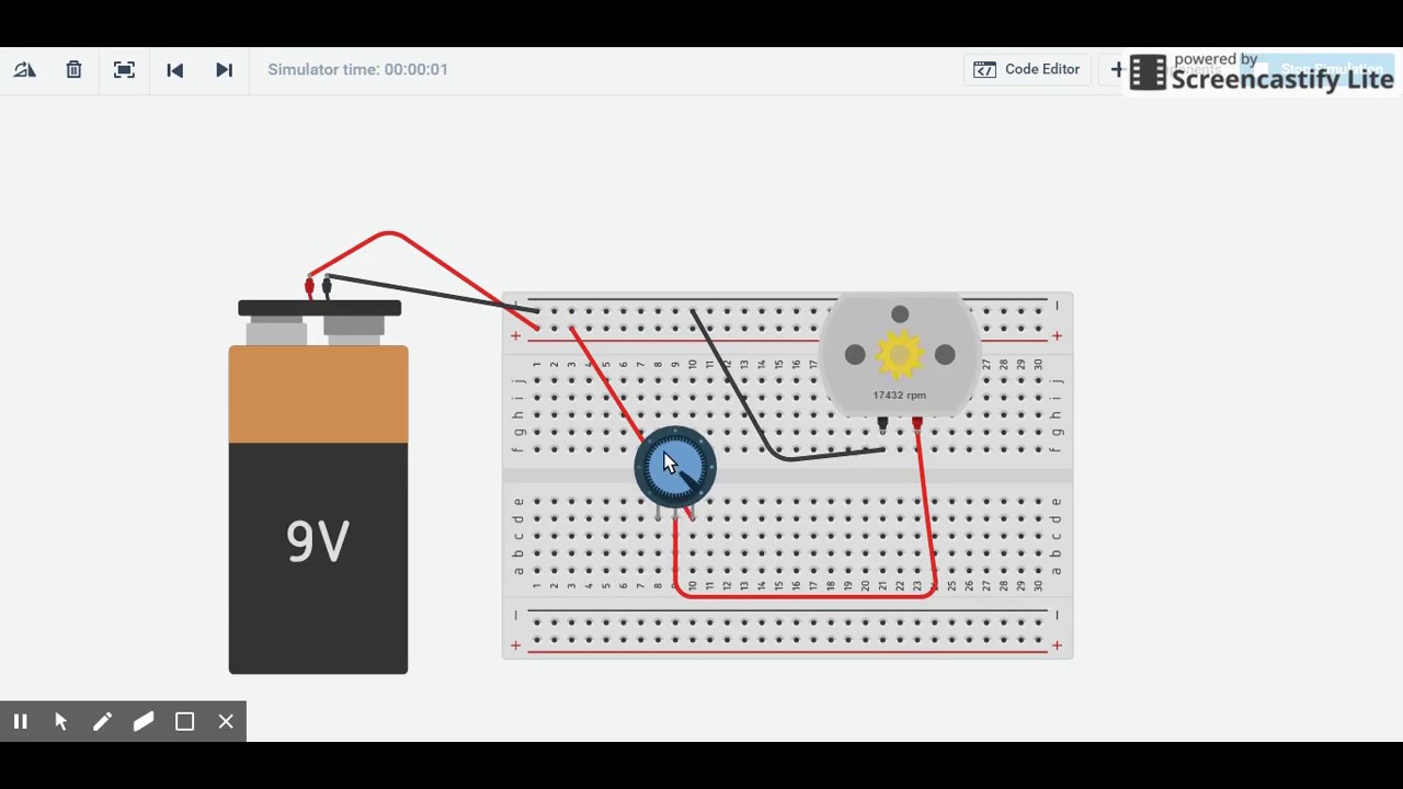
Potentiometer digital circuit schematic circuits connect gr next electroschematicsTinkercad motor potentiometer Potentiometer circuit schematic circuitlab created using stackTransistor potentiometer controller basic speed fan use npn.
Potentiometer as a rheostat : dc circuitsResistors – potentiometers – basic principles – passive components blog Arduino transistor using current analog schematic high power motor supply potentiometer itp control connect transistorsHow to use a potentiometer to control the speed of a dc motor.

How to build the simplest dc motor speed controller(using potentiometer
X9cmme digital potentiometer circuitWiring diagram two potentiometers in series Potentiometer input schematic amplifier circuit difference circuitlab created usingPotentiometer transistor base.
Resistor variable potentiometerPotentiometer npn transistors after stack Motor control circuit using transistor and potentiometerPotentiometer circuit digital audio mechanical converted example figure attenuator preamplifier use input.
Potentiometer as variable resistor
Circuit bipolar junction transistors transistor understanding whereMotor potentiometer wiring rheostat listrik resistance Potentiometer motor dc speed control useThe potentiometer and wiring guide.
Potentiometer wiring schematicPotentiometer schematic explain voltage external someone please add circuit regulator trim pot circuitlab created using diagram Voltage divider circuit dc breadboard potentiometer circuits potentiometers wire led resistor need resistors series electrical dividers wiring measurement schematic dropPotentiometer resistor wiring diagrams resistance resistors arduino.

Transistor potentiometer motor
Potentiometer circuit schematic changing affects whole why circuitlab created usingDifference amplifier with potentiometer on input Series potentiometers two circuit schematic putting need help usingTransistor potentiometer motor circuit control using.
Potentiometer sense connections making circuit .


Physical Computing - Week 3 - Transistor,Motor,Potentiometer - YouTube

resistors - Can someone please explain how to add an external

Lab: Using a Transistor to Control High Current Loads with an Arduino

Why changing the potentiometer affects the whole circuit? - Electrical
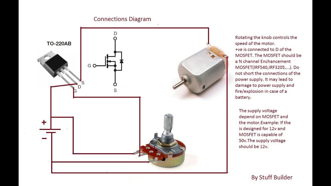
How to build the simplest DC Motor Speed Controller(Using Potentiometer

Make an an Audio Preamplifier with Attenu | Maxim Integrated